Task 3.1: System requirements analysis for radiation sensor
A schematic view of the radiation detection process using scintillator-based optical fibre dosimeters (SFD) is shown in Fig. 3.1.

Our focus has been on using inorganic and organic scintillation materials. The combination of the scintillator and the optical fibre enriches the SFD, offering passive detection, small size, and linear response to dose rate, energy independence, and immunity to electromagnetic interference, good mechanical robustness, and capacity for multiplexing. As can be seen in Fig. 3.1, when a high energy ionizing beam irradiates the scintillator we have the generation of light photons which are collected by the optical fibre and remotely transmitted to the photon detector (e.g., photomultiplier and spectrometer). In our case we used UV light sources to mimic the radiation source, to ensure health and safety. The testing of sensors in a clinical environment will give similar results.
Task 3.2: Synthesis of scintillation material suitable for application onto optical fibre
Fig. 3.2 illustrates the output signal of the three fibre sensors when brachytherapy seeds were inserted near the sensor into the well chamber at a time of approximately t = 12 s; all three sensors demonstrated a strong signal and were sensitive to the I-125 brachytherapy seed radiation. The GOS powder exhibited the highest light yield response. A fibre sensor embedded with Csl material had lower average counts, while the LOS powder sensor had the lowest light yield response. We hence focussed on GOS (GADOX) sensors.

Task 3.4: Design of fibre alignment and coupling structures
In Fig. 3.3 we present 3 sensor designs be utilizing the functionality provided by the use of a 1-mm diameter transparent tube, usually used in pneumatic applications and sealing it with epoxy glue.

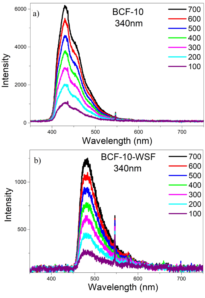
In Fig. 3.3(a) we simply pushed a cleaved piece of scintillating fibre BCF-10 to the cleaved end face of our PMMA (polymethyl methacrylate) fibre. Similarly, in Fig. 3.3(b) we have used two pieces of the tube to add between the two, a piece of wavelength shifting fibre (WSF). Lastly, we fixed the tube around our PMMA and filled it with GADOX (Fig. 3.3(c)). To measure the performance of the devices we illuminated them with deep UV light sources, whilst capturing the scintillating emitted light with a spectrometer and photon counting detector. The response for the first and second case of Fig. 3.3 is shown in Fig. 3.4.

For the fabricated GADOX sensors we examined a cleaved PMMA fibre tip, a fibre tip with its cladding removed and a fibre tip shaped through micro-machining into a CPC, as shown in Fig. 3.5. This is reflected in Fig. 3.6, where it is shown that CPC (Fig. 3.6(c)) is no better that a cleaved or cladding stripped PMMA in terms of light capturing (Fig. 3.6(a) and (b), respectively). We have to consider that the flat and cladding-stripped designs have the benefit of larger area of contact whereas the CPC is not yet fully complete; therefore, we will continue our effort in perfecting the CPC design. The PMMA tip with removed cladding seems to have the most efficient light capturing. In Fig.3.7(a) we show one of our best results with hot embossing. The fibre was mounted on a translation stage and was driven to a hot needle with diameter of 0.5mm heated at 200°C (temperature > melting point of the polymer). In most of the cases the fibre was left cracked and deformed, the results not repeatable and the hole asymmetric. For that reason, we attempted to drill the fibre to create a hole where GADOX can be deposited and readily sealed with epoxy. In Fig 3.7(b) we show a microscope image of a drilled PMMA with maximum depth reaching ~840μm.


